Call us on 01634 729 690
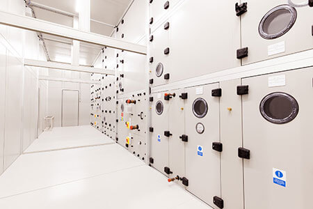
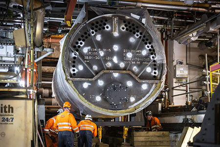
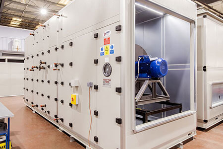
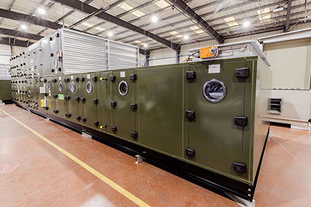
In our forty-year history, ECE has produced thousands of air handling units for sites all over the country. We have completed a huge range of complex projects for top principal contractors such as Kier and Morgan Sindall, and at historic sites like Battersea Power Station and Imperial College London. We’re proud of what we’ve accomplished and are always eager to display the quality of work you can expect for your project.
Impressed with our
work? Get in touch
Our team can bring the same impressive level of skill you see here to your project. Call 01634 729 690 or email sales@eceuk.com to discuss a custom air handling solution for your site.