Gravity or pressure relief damper (PRD)
The Gravity Damper schematic (Figure 1), with pressure relief being the focus, working alongside a Supply Secondary Air Unit (SSAU), can maintain good indoor air quality and pressure equilibrium in an HVAC system—i.e., ensuring the area served is not over-pressurised.
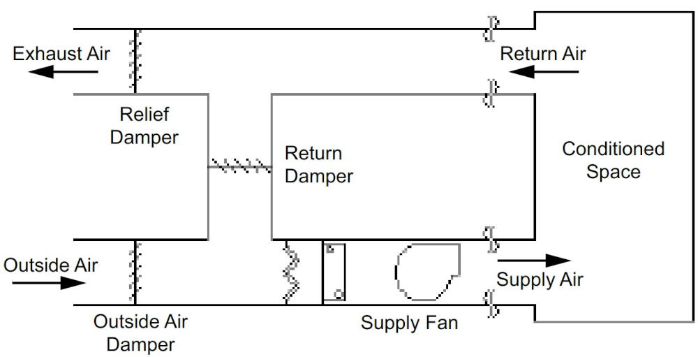
Figure 1: Pressure Relief Damper Schematic
Gravity damper mechanism
By utilising gravity-operated relief dampers (Figure 2), it effectively allows for excess air to be released from the building when the indoor pressure exceeds the outdoor pressure, thus preventing over-pressurisation.
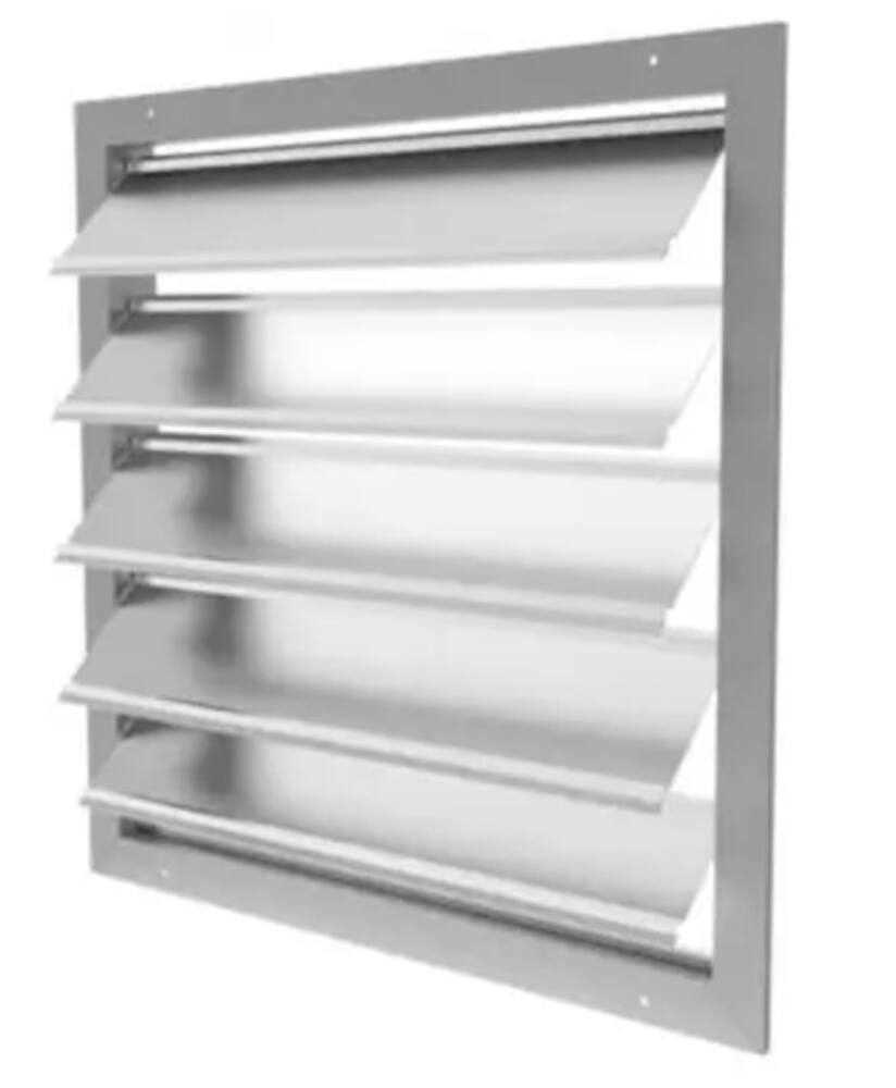
Figure 2 Gravity or Pressure Relief Damper
Key features and functions:
Automatic response
The damper’s blades automatically adjust based on the pressure difference between indoor and outdoor air.
- When the indoor pressure exceeds the outdoor pressure (positive pressure), the relief blades open, allowing excess air to escape.
- Under negative pressure, the blades seal shut to prevent uncontrolled outside air infiltration
The exact response of the fresh air damper and recirculation damper (Figure 3) depends on the control logic and sensor inputs. For instance, the fresh air damper typically reduces outdoor air intake, while the recirculation damper opens more to maintain airflow and comfort within the AHU. The correct control logic implements a true/false scenario to lock or freeze the dampers when a pressure relief damper opens. Regular air handling unit maintenance is essential to ensure optimal damper performance and HVAC efficiency
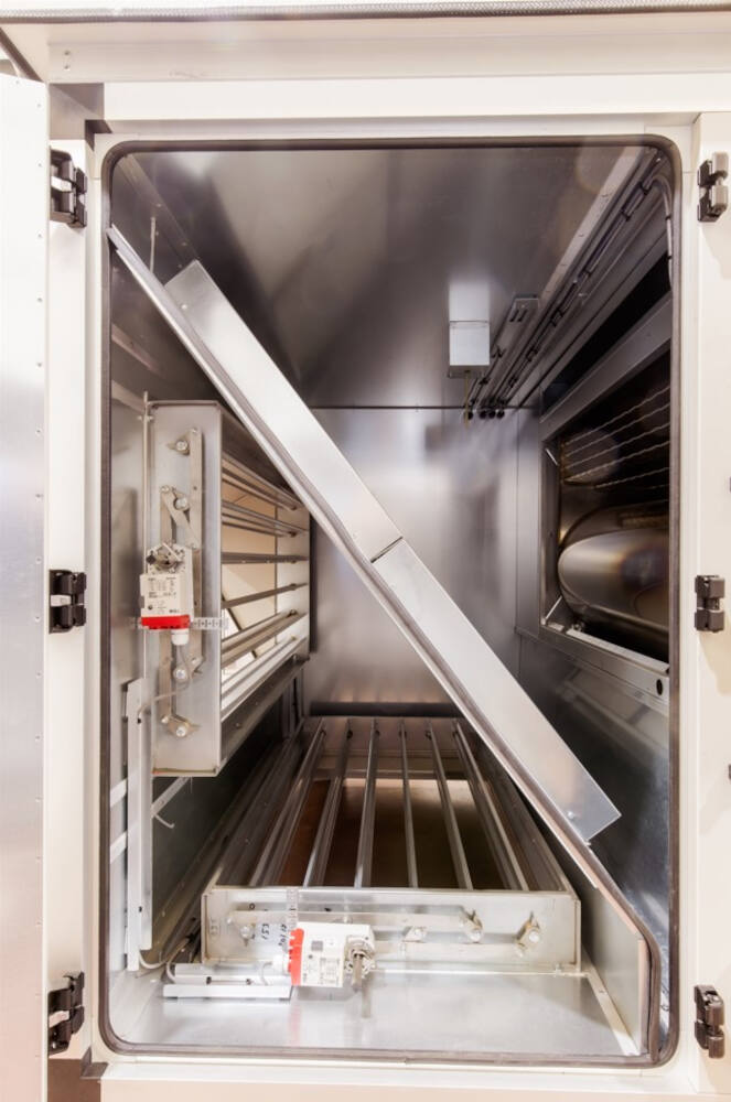
Figure 3: Fresh Air and Recirculation Damper (SSAU)
Location
Positioned on the return air side of the fan, the AHU pressure relief damper ensures the indoor fan does not over-pressurise the space, avoiding discomfort, air quality degradation, or damage to HVAC system components.
Energy efficiency
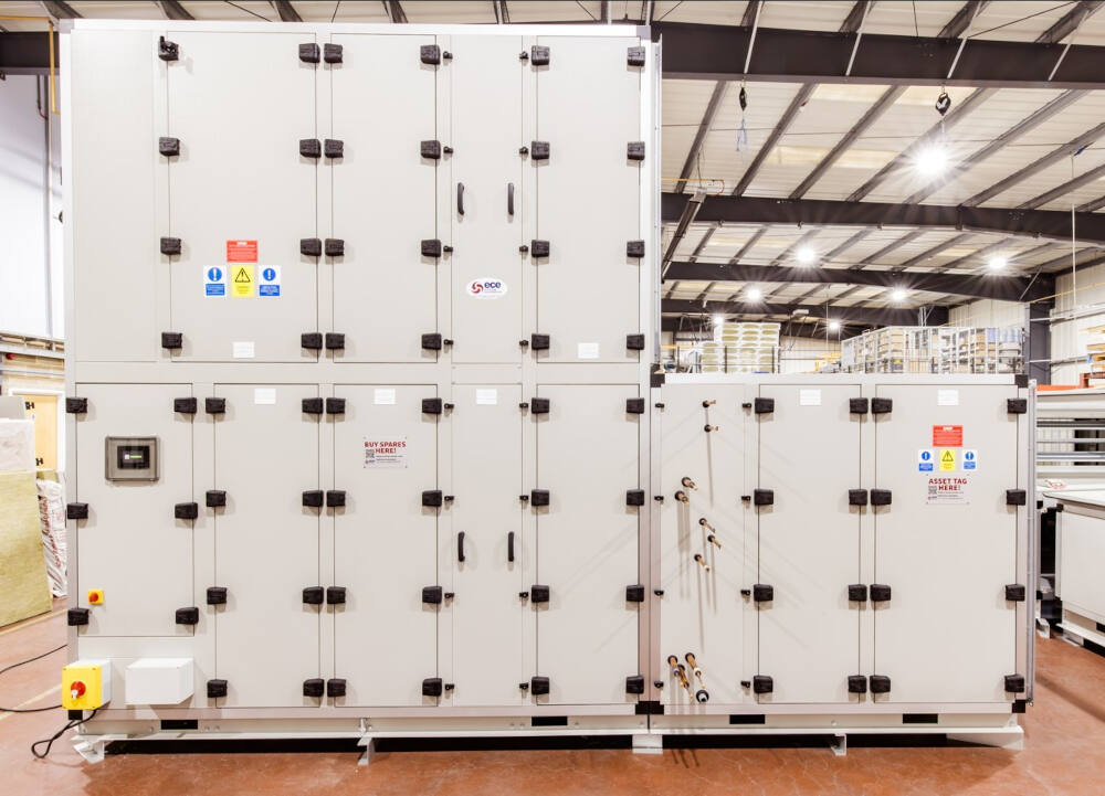
It supports efficient HVAC airflow regulation by allowing controlled air release. When paired with Demand Control Ventilation (CO₂ control) and SSAUs (Figure 4), buildings can reduce energy usage by adjusting ventilation based on occupancy.
Demand Control Ventilation (CO2 Control) and Supply Secondary Air Units (Figure 4) can be used with a pressure relief damper; buildings can reduce energy consumption by adjusting ventilation based on occupancy rather than maintaining constant airflow. This adaptability leads to significant savings in heating, cooling, and ventilation energy use.
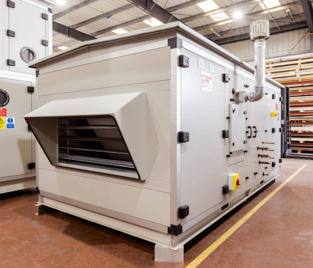
Figure 4: Supply Secondary Air Unit (SSAU)
Simplicity and reliability:
This passive mechanical device operates without additional power or complex systems, offering a dependable, low-maintenance solution for pressure control in HVAC.
Application:
Gravity Damper systems are prevalent in mechanical ventilation systems for healthcare facilities, laboratories, cleanrooms, and data centres where air balancing dampers and pressure management are vital. They can be especially beneficial in buildings with high ventilation demands or varying occupancy levels.
Benefits
- Improved air quality: Prevents over-pressurisation to maintain healthier indoor environments with appropriate HVAC air distribution.
- Comfort: Helps maintain consistent indoor conditions, leading to improved comfort for occupants.
- System protection: Reduces stress on the HVAC system, prolonging the lifespan of components and minimising repair needs.
In summary, the pressure relief damper is vital for maintaining balanced air pressure, enhancing energy efficiency, and improving HVAC system balancing, all while supporting better air quality and occupant well-being.
Role of 3-way air mixing plenums in modern HVAC systems
Incorrect positioning of exhaust fan with a 3-way air mixing plenum
The Exhaust Fan and 3 Way Air Mixing schematic (Figure 5), shows the exhaust fan positioned on the negative side of an SSAU. This setup disrupts HVAC airflow regulation and cannot maintain the required indoor air quality, HVAC, or pressure balance. Poor air plenum design compromises unit performance, temperature control, and fresh air supply.
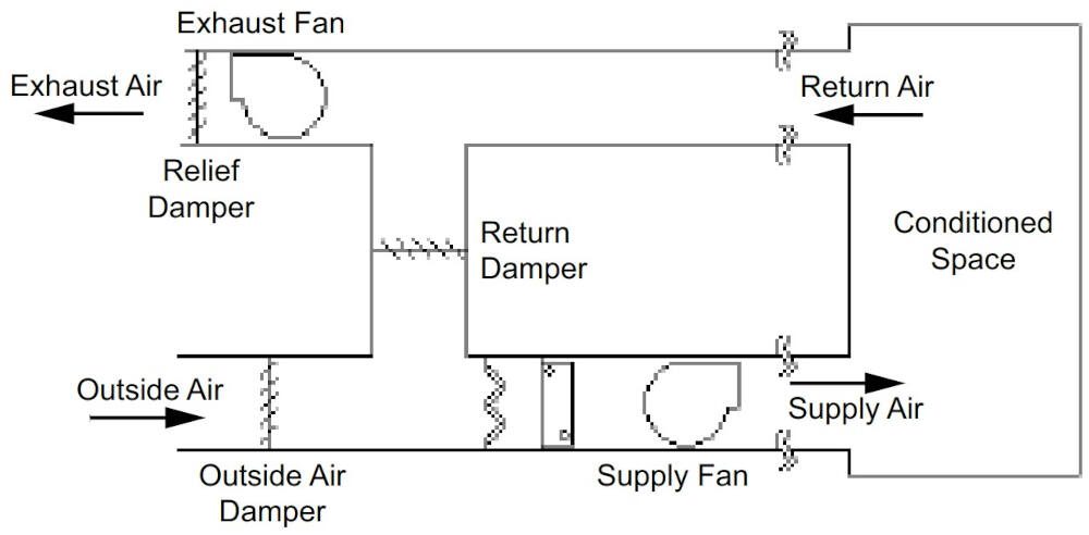
Figure 5: Exhaust Fan and 3 Way Air Mixing Schematic
Role of 3‑way air mixing plenums in energy efficiency
Pressure dynamics
Transitioning from 100% outside air to mixed air can create unintended airflow paths. If the outside air damper closes as return air flows in from the wrong direction, pressure may rise. The exhaust fan (Figure 6), drawing from a low-pressure mixed air plenum instead of the building, leads to incorrect airflow and HVAC air distribution issues. Thus, if the outside air damper is not adequately controlled it can lead to incorrect airflow patterns.
Figure 6: Exhaust Fan
Energy efficiency challenges with misplaced exhaust fan
The following challenges occur with this design when installing Demand Control Ventilation (DCV) i.e., CO2 control.
- Pressure imbalances – If the return air plenum experiences a more negative pressure than the design requires, it can cause unintended airflow patterns. This could lead to challenges for DCV systems, which rely on accurate sensing of air quality and occupancy to adjust ventilation rates effectively.
- Response delays – DCV systems are typically designed to adjust ventilation rates based on real-time data from sensors (e.g., CO2 levels). If the economiser system improperly modulates the outside air damper due to pressure conditions, it may not respond quickly to changes in occupancy or air quality, leading to potential comfort issues or energy waste.
- Inadequate air mixing – The high velocity and negative pressure conditions in the mixing plenum can hinder proper air mixing, a critical aspect of both recirculation and DCV. Without adequate air mixing, some areas of a space may receive insufficient ventilation, while others may become over-ventilated, negating the benefits of DCV.
- Increased energy use – Poor design leading to excess pressure drops and inefficient airflow can significantly increase the energy required to operate the system, counteracting the energy-saving potential of both recirculation and DCV.
Negative pressure management
A well-designed system ensures that the pressure drop in the return plenum is less negative than that in the mixing plenum during recirculation operation for instance exhaust fan positioned so it pressurises the exhaust damper and recirculation damper (Figure 7). The return fan allows the supply fan to effectively draw return air without incurring excessive power losses. Proper pressure differentials are key to maintaining air plenum design integrity and indoor air quality.
Figure 7: Exhaust fan pressurising the exhaust and recirculation dampers
In summary, while it is possible for poorly designed recirculation systems to work with DCV, their combined effectiveness will be suboptimal and may lead to inefficiencies and occupant discomfort. To achieve the intended benefits of both systems, it is essential to redesign the system to ensure proper pressure relationships, airflow patterns, and control integration, addressing the shortcomings typically associated with poor design. Ultimately, a thoughtful design approach can lead to a more efficient and responsive HVAC system that optimally utilises both free cooling strategies and demand control ventilation principles.
Correct Positioning of Exhaust Fan with a 3 Way Air Mixing Plenum
The Exhaust Fan and 3 Way Air Mixing schematic (Figure 6), shows the fan positioned on the positive side of an SSAU or Supply & Extract Unit 3 Way Mix (SEU3MX). This set up can maintain good indoor air quality and pressure equilibrium in a HVAC system.
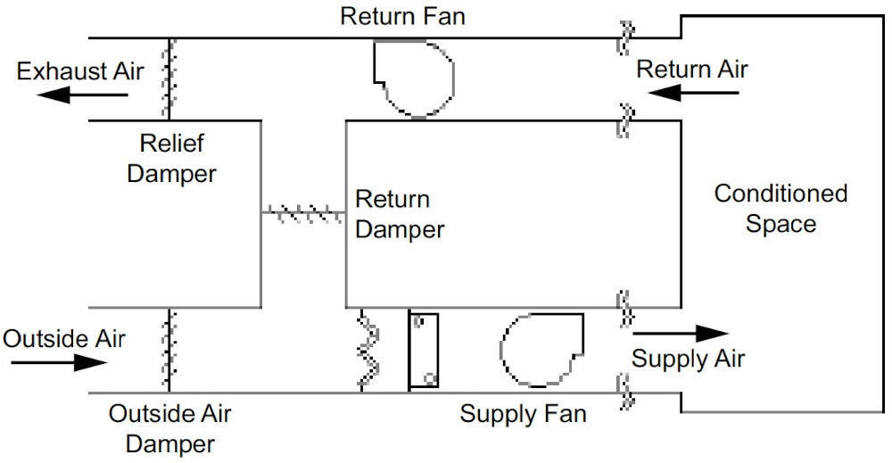
Figure 6: Exhaust Fan and 3 Way Air Mixing Schematic
If provided with demand control ventilation (DCV), the correct sizing and design of the supply and return ducts are critical for optimising performance and maintaining acceptable indoor environmental quality. Below is an overview and key design considerations involved in managing supply and return airflows within such a system, particularly regarding exfiltration and its impact on space pressure.
Overview
A return fan positioned on the positive side of return damper (Figure 7) employs the return air to promote energy efficiency by reusing existing conditioned air, particularly when outdoor conditions are favourable for cooling or ventilation. Coupled with demand control ventilation, this system effectively optimises indoor air quality while minimising energy costs.
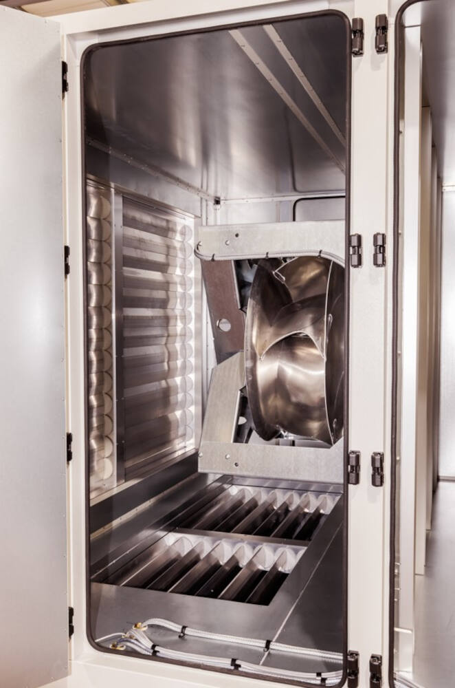
Figure 7: Exhaust Fan with Recirculation and Exhaust Damper
Key Design Considerations
1. Maximum Airflow Capacity:
- Supply and Return Duct Design: The supply and return ducts should be sized to handle the maximum supply and return airflows (in metres cubed per second, or m3/s) the system is intended to accommodate. This ensures that there is sufficient capacity for airflow, particularly during peak demand conditions.
2. Exfiltration:
- Definition and Impact: Exfiltration is the process by which conditioned air leaks out of the building through openings in walls, around doors, windows, and other structural components. The amount of air that can exfiltrate largely depends on:
- The space static pressure: Higher pressure differential leads to increased exfiltration rates.
- Building construction: Materials, construction quality, and air sealing techniques directly influence the permeability of the building envelope, affecting how much air escapes.
3. Space Pressure Management:
- Maintaining Acceptable Space Pressure: It’s vital to maintain a balanced indoor air pressure to avoid negative (or positive) pressure conditions that could lead to issues such as:
- Air quality problems, whereby pollutants may enter from outside or from adjoining spaces due to pressure differences.
- Unintended thermal losses.
- Increased energy consumption from HVAC systems trying to compensate for inflation/deflation of the building envelope.
Benefits
Correctly positioning the return fan in a 3 Way Air Mixing Plenum designed for demand control ventilation (DCV) applications offers several significant benefits in terms of energy efficiency, indoor air quality, comfort, and operational flexibility. Below is a detailed look at these advantages:
1. Energy Efficiency
- Reduced Energy Consumption: By utilising return air for minimising reliance on mechanical heating and cooling when outdoor air conditions are favourable, the system can significantly lower energy use. This results in lower utility bills and a reduced carbon footprint.
- Optimised Fan Operation: The system adapts fan operation based on occupancy and ventilation needs, allowing for reduced airflow when the space is under low demand, further conserving energy.
- Free Cooling Opportunities: During cooler weather, the economiser can bring in fresh outdoor air, reducing or eliminating the need for mechanical cooling altogether, thus maximising the efficiency of the HVAC system.
2. Improved Indoor Air Quality (IAQ)
- Enhanced Ventilation Control: DCV optimises the amount of fresh air introduced into the space based on actual occupancy and pollutant levels. This leads to better indoor air quality as it adjusts ventilation rates according to real-time needs.
- Targeted Response to Pollutants: By monitoring CO2 levels or other air quality indicators, the system can provide increased ventilation during high occupancy, ensuring that indoor pollutants are effectively diluted.
3. Cost Savings
- Lower Operating Costs: Decreased energy consumption translates directly to lower operating costs for HVAC systems, improving overall cost-effectiveness over time.
- Reduced Equipment Wear and Tear: By allowing for lower levels of air conditioning when outdoor conditions permit, the life span of HVAC equipment may be extended due to less frequent operation under full load conditions.
4. Occupant Comfort
- Consistent Temperature Control: Effective management of the airflow can result in improved temperature control, preventing hot or cold spots in the occupied space.
- Proactive Response to Demand: Since the system adjusts based on actual attendance and occupancy, occupants receive adequate ventilation without unnecessary fluctuations in temperature or airflow, contributing to overall comfort.
5. Flexibility and Adaptability
- Response to Varying Occupancies: DCV systems can quickly adapt to changes in occupancy levels, providing ventilation based on real-time data rather than relying on a static schedule, making them ideal for spaces with fluctuating use.
- Scalability: These systems can be designed to easily accommodate changes in building layout, occupancy loads, or usage patterns without significant redesign, making them a flexible solution for dynamic environments.
In summary an SSAU or SEU3MX system designed correct with demand control ventilation (DCV) applications provides a holistic approach to optimising HVAC performance while ensuring high indoor air quality and occupant comfort. These systems leverage energy-efficient practices and adaptive ventilation strategies to accommodate actual building needs, fostering a sustainable and responsive indoor environment. This makes them increasingly prevalent in good building designs focused on energy efficiency and occupant health. For high-performance solutions, partner with a trusted Air handling units Manufacturer offering modern HVAC technologies.